

We will try some exciting circuits in the coming blogs. The crucial skill of interpreting circuit diagrams cannot be ignored. Similar to preparing a food recipe, a crucial skill is to know the ingredients, proportion thereof and when to add in the making process as well as a power source to be low or high flame, microwave etc.
Similarly to get desired output from a circuit; two tasks are important:
(i) Knowing the components (Polarity, Value, Unit): When an electronic component needs to be connected in one direction, it is said to have polarity.
Circuit diagrams work on sign language. Components are represented by their symbols and not by their physical appearance because it is universal. Components having the same specification may have different look and type of construction at different places; however, their symbols have common standards universally.
The value of the component is labelled on the component’s symbol in the diagram.
(ii) How to make connections
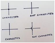
Circuit diagrams are basically maps, which indicate particular components to be connected in a particular sequence. The lines drawn between the components are the electrical connections to be made using connecting wires. If a line is drawn between components, that means they are connected.
In a diagram, if the wires are connected, they are shown with a dot at the intersection. Unconnected wires are shown without a dot or with a bridge or crossover.
This article will make your component identification process easy and will also aid in making circuits.Let us discuss some components, how they look and how to fix them in a circuit. Few commonly used components are listed below:
1. LED: Light Emitting Diode


- Two Terminals: Longer leg Positive Shorter Leg Negative
- If you look inside the LED, the broader lead is Cathode (negative)
- Lead looking almost straight is Anode (positive)
- In a circuit diagram: Positive is represented as +ve and negative as –ve
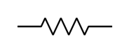
- Resistor:
- Two terminals device.
- No Polarity: can be connected either ways.
- Unit: ohm Ω
- Higher units: 1000 Ω = 1 Kilo Ohm (KΩ)
- 1000 KΩ = 1 Mega Ohm (MΩ)
- 1000 MΩ = 1 Giga Ohm (GΩ)

3. Variable Resistor:


- Capacitor:
- Unit Farad (f); milli farad (mf); micro farad (µf); nano farad (nf); Pico farad (pf)
- Ceramic capacitor: Two terminal device.
- No polarity: can be connected either way.


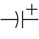
- Electrolytic capacitor: Two terminal device: Longer leg positive; shorter leg negative
- Unit: microfarad

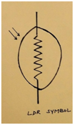
- LDR:
- light dependent Resistor
- Two terminal device.
- No polarity can be connected either way.

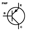
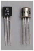
- Transistor:
- Three terminal device: Base, Emitter and Collector.
- Two types : PNP and NPN
- The direction of emitter arrow defines the type of transistor.
- Data sheet states which lead is emitter, base or collector.


- Speaker:
- Two terminal device.
- No polarity can be connected either ways.


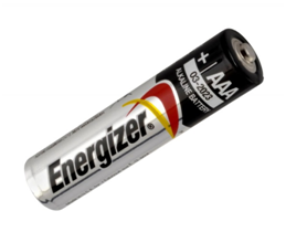
- Cell holder:
- Side with spring is negative.
- Flat side of the cell is negative.

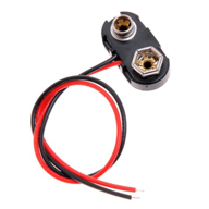
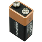
- Snap :
- For 9V battery.
- Red wire Positive, Black Negative.
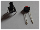
- Switch: Can be connected either ways


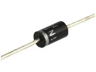
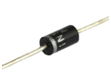
- Diode : Side with ring is negative.

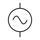
- Power Source: We need to energize the circuit. This source can be A.C or D.C.
- A.C Source: The circuit may need to be connected to mains or any other alternating current source. It is represented as:
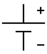
- DC Source: Cell and batteries provide direct current (D.C). Sometimes battery eliminator or adaptor is used in a circuit as source of D.C. They basically convert A.C into D.C.


| Component | Symbol | Physical appearance |
| LED | 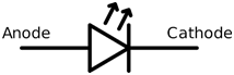 |
 |
| Resistor |  |
 |
| Variable Resistor | 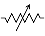 |
 |
| Ceramic Capacitor | 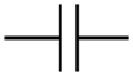 |
|
| Electrolytic capacitor |  |
 |
| Light Dependent Resistor (LDR) |  |
|
| Transistor |   |
 |
| Speaker |  |
 |
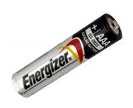
| Cell | 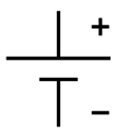 |
 |
| Battery | 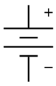 |
 |
| Switch | 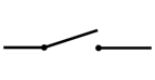 |
 |
| Diode | 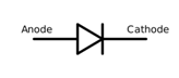 |
 |
Nice blog mam as we can recall every thing we have done till now. And also we can get to know about many new things.
Got to know about many older and new things.