

Crossing Danger
Pick the button
In this article, we will learn to assemble a simple electronics circuit. This is not only a learning activity – you can also develop multiple games using this circuit to enjoy yourself and impress your friends. In carnivals, Diwali mela or fete, you can display these games and even earn pocket money also.
We will use a special purpose PCB designed for this circuit. No wiring is needed with such PCB. We just have to place the components at the designated place on component side and solder them properly on the reverse side (solder side). On the solder side, there are conducting tracks inscribed instead of wire connections. This makes the circuit neat, crisp and less cumbersome.
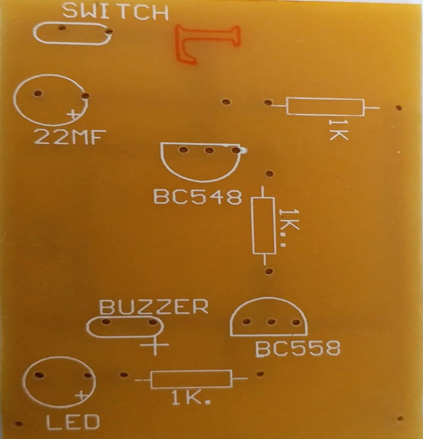
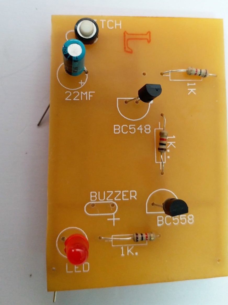
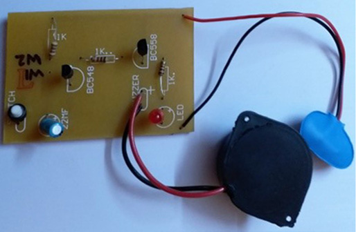
COMPONENT SIDE OF PCB
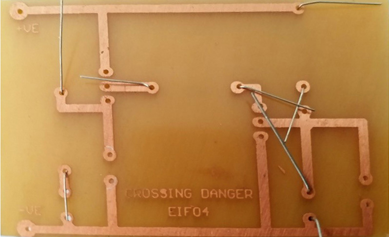
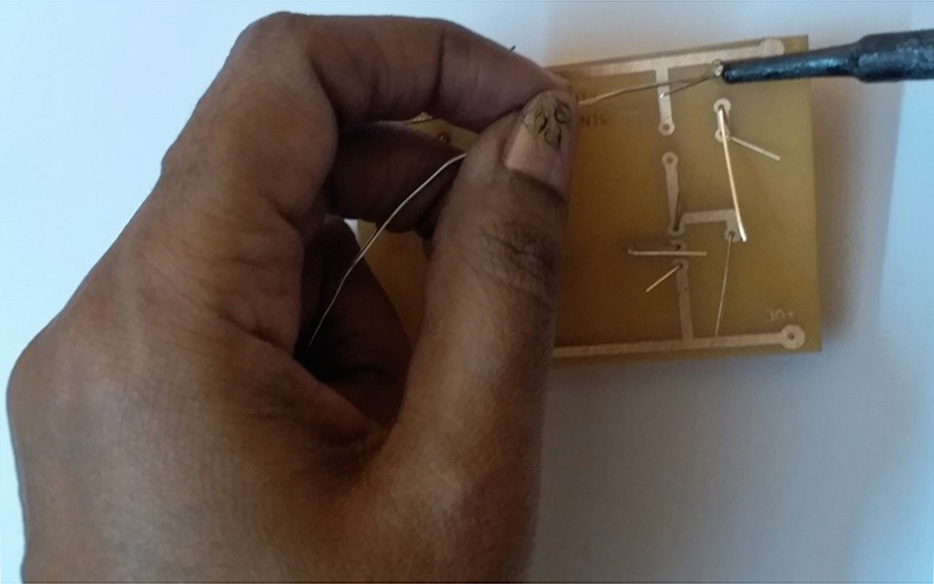
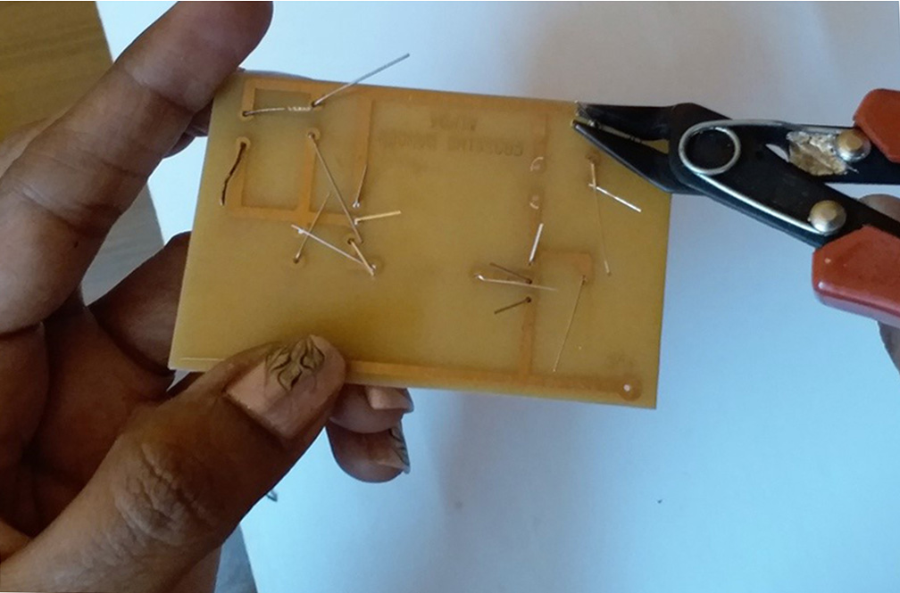
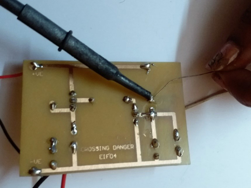
SOLDER SIDE OF PCB
1. First step is to prepare a CID Chart (Component Identification Data). We need to inspect each component, check its value and mark the polarity.

2. Mount the resistance as per the markings on the PCB. They do not have any polarity and can be put in any direction. Bend the component’s lead after mounting so that it does not fall when we turn the PCB for soldeling.
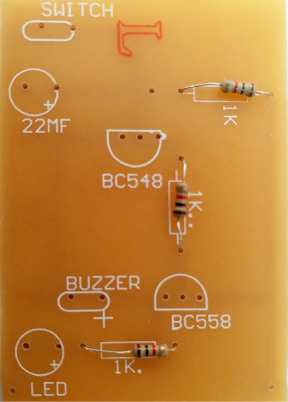
3. Mount the transistors as per their value and match the direction of mounting with the PC . The electrolytic capacitor and LED are also mounted as per polarity. The switch can be mounted in any direction. Bend the component’s after mounting.
4. Turn to the solder side of the PCB. Turn on your soldering iron. Let it heat sufficiently. Straighten the lead of component which you want to solder. Cut the extra lead after soldering.
5. Now prepare buzzer wires for soldering (cut, peel, wrap). Insert the red wire of buzzer at the hole marked +on PCB and blackwire in the other hole. Solder the buzzer.
6. Two holes are marked +ve and –ve on the solder side of PCB. Insert the snap wires for 9V battery accordingly.
7. Now is the game time. Two points are marked W1 and W2 on the circuit. Take out two wires from these points. Tin wire can be used as one of the wire.
TIN WIRE
8. Connect the 9V battery to the snap. Join the wires w1 and w2. The circuit will start buzzing. Now disconnect the wires (w1 and w2) and press push to on switch to reset the circuit.
9. You will observe every time we join the wires w1 and w2, the circuit starts buzzing, disengage the wires and reset the circuit by pressing the switch. This special feature of the circuit is used to construct interesting and engaging games of eye hand coordination.
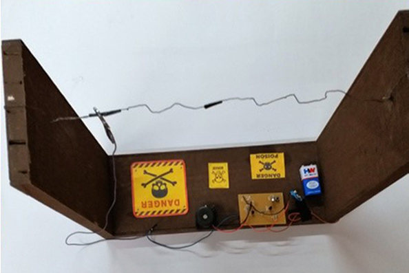
Game 1: Crossing Danger
- One of the wires used in the circuit is tin wire, which can be placed in zig zag manner as bridge. The other wire is soldered to the key. The player will hold the key and attempt to guide the key along the bridge. When the key touches the bridge wire, buzzer rings and it is a foul.
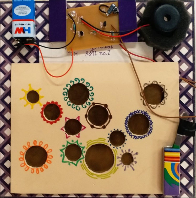
Game 2: Pick the Button
The player has to pick the button using tweezer, from a metal tray without touching the metal tray. If the tweezer touches the tray, the buzzer will signal a foul. Funny, isn’t it?
Recent Comments