
Electronic Harmonium is a simple circuit that generates notes/swaras of Indian classical music system. These notes are sa, re, ga, ma, pa, dha, ni. These seven distinct notes are collectively called Sargam.
This circuit demonstrates the need of electronics in diverse fields like music in life. Let us see as to how we can transform a circuit into a melodious instrument by using simple electronic components.
Let’s get going!
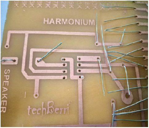
CIRCUIT LAYOUT
The circuit layout shows the placement of different components (values, polarity). We just have to insert the components at the designated place and solder them properly on the reverse side. On the solder side, there are conducting tracks inscribed instead of wire connections. This makes the circuit neat and easy to make.

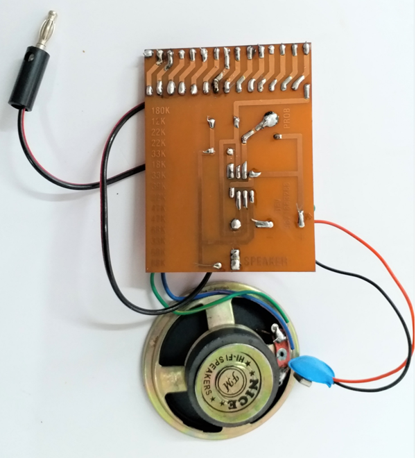
Circuit description
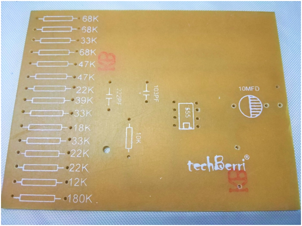
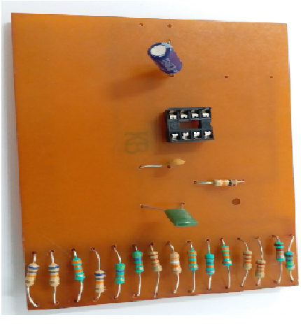
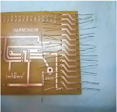
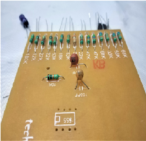
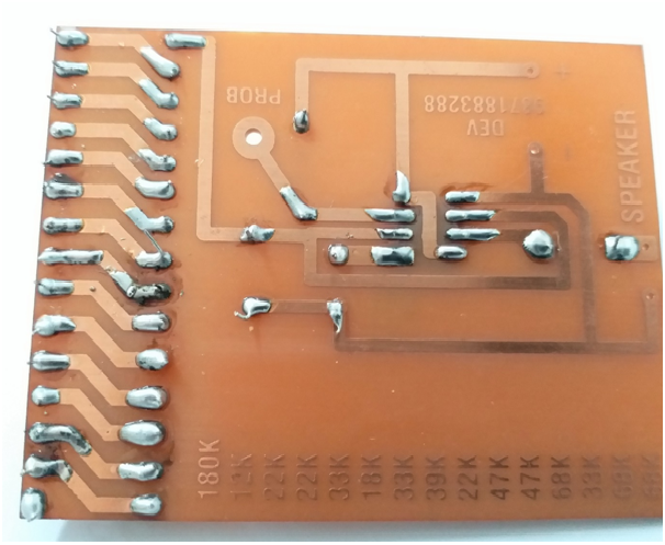
The circuit consists of a specially designed PCB, with 15 parallel copper tracks. The resistance of different values is mounted on each track as per layout. Each resistance corresponds to one note. So, as the probe touches different resistance, different notes are generated.
The circuit is built around IC 555. When we put the probe on different resistances, we are effectively changing the frequency between pin 2, pin7 of the IC 555.
Component side of PCB
This is the side where we will mount the components.
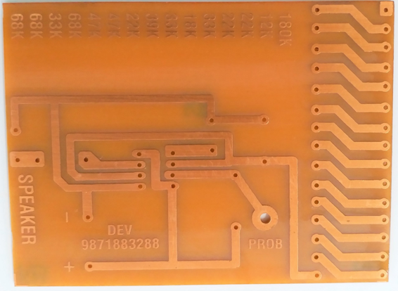
Solder side of PCB
Solder side contains conducting tracks to make the connections between various components. We will fix the components at their designated place by soldering.
Now follow these steps to start building the electronic harmonium:
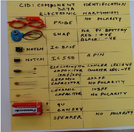
1. Prepare the component identification data (CID) for the circuit.
2. Insert the components according to circuit layout while taking help from the markings on the PCB.
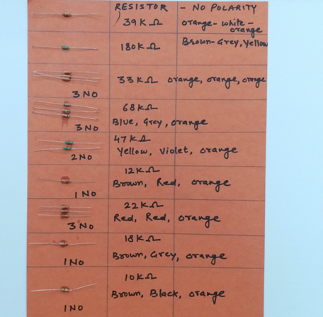
3. First mount the resistors. For the values refer to pictures as well as the post on Resistor: Value reading. Since the resistors do not have any polarity, they can be mounted either way. Turn over the PCB and bend the leads to prevent them from falling.
4. Now mount the ceramic capacitors with 222PF capacitor and 103PF capacitor according to the markings and circuit diagram. Bend the legs after mounting to prevent them from falling.
5. Now mount the IC base and the electrolytic capacitor. The electrolytic capacitor has polarity. Mount the IC base as per the notch direction on PCB. Bend the legs of the electrolytic capacitor normally but bend any two opposite pins on the IC base to prevent it from falling. Refer to the picture below :
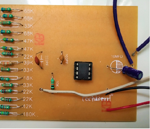
6. Solder all of the points and cut off all the leads.
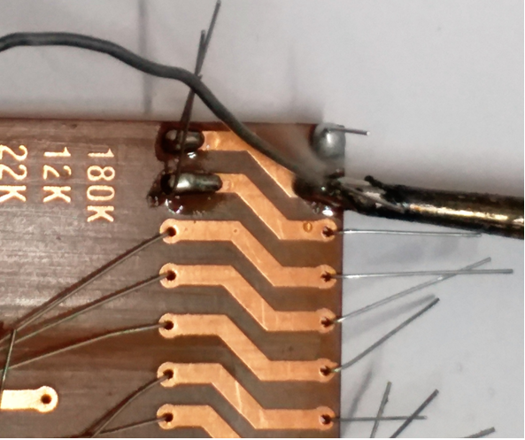
7. Prepare the 9V snap, probe wire and two additional wires for the speaker by striping them and soldering them to their points. refer to the Diagram and pictures below.
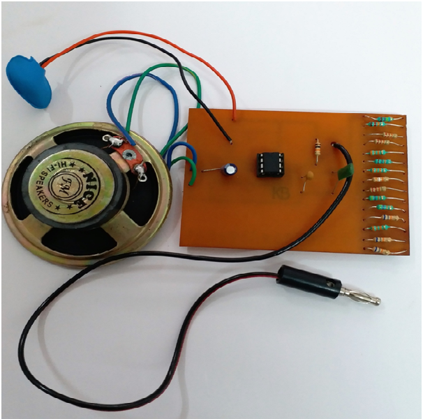
The circuit is ready. Enjoy the melodies!!!
Recent Comments